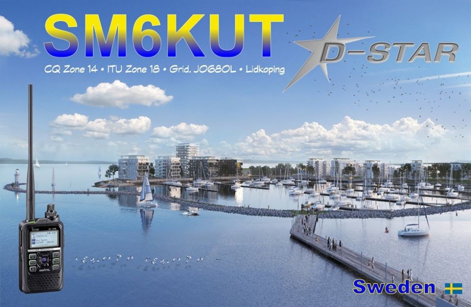
D-Star and ALLSTAR
And also qrv on Dstar, and I mostly stay REF1C and REF30C when I'm qrv.
I am now qrv via Allstar and usually East Coast REF 45225 . and Alaska morning net 29332 . And via ALLSTAR SWEDEN 553415, and ALLSTAR SWEDEN 553417.
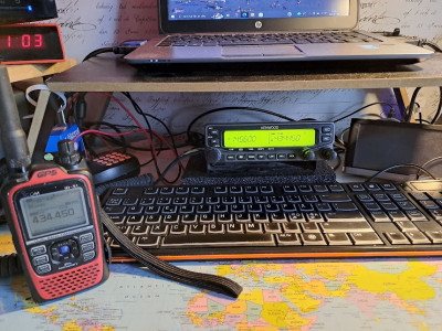
And very nice to be able to use my old radios which I haven't done in a while.
So I hope we can get a qso on Allstar some day.